Hi, I'm Drew Taylor
Aerospace Engineer driven by curiosity and a passion for advancing the future of flight and space exploration.
Design. Analyze. Build. Test.

Model CubeSat
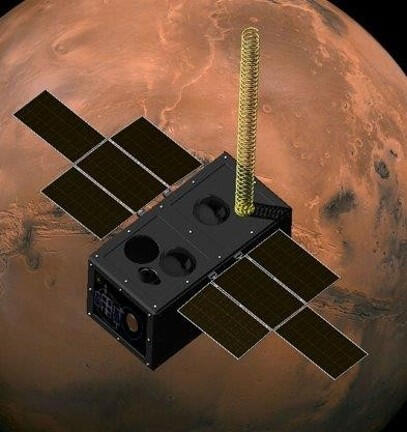
M.A.R.V.E.L.

Flight Tracker

Scoop Holder
SENIOR DESIGN MODEL SMALL SAT
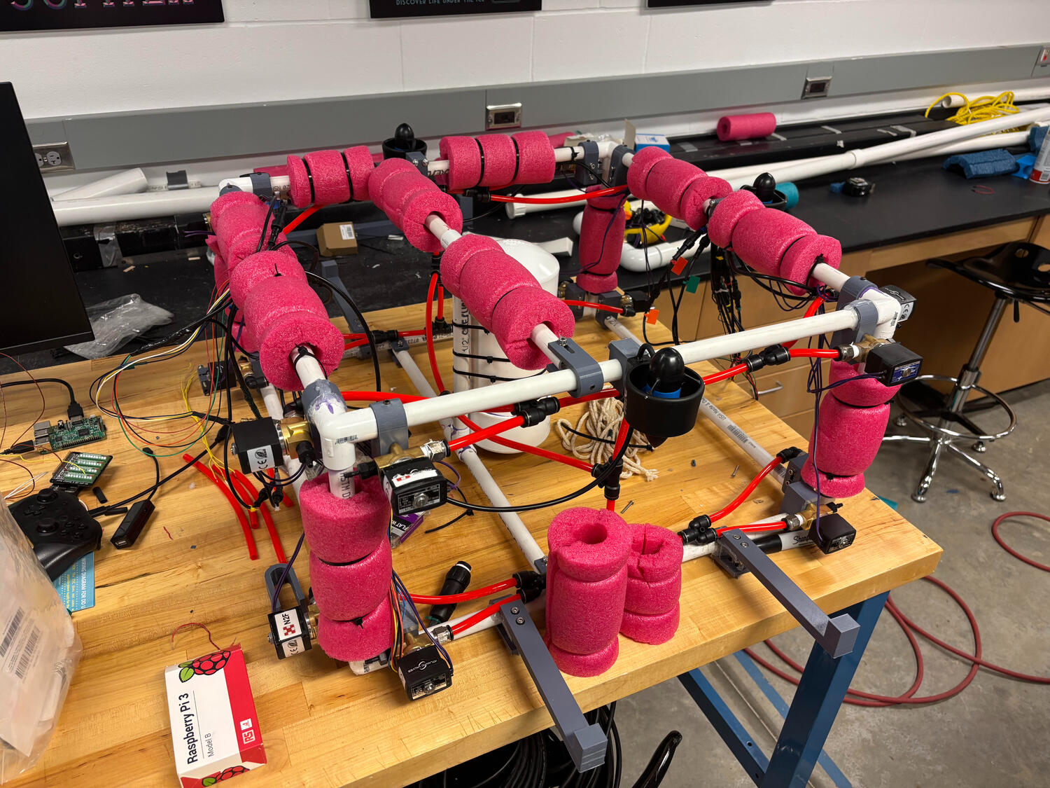
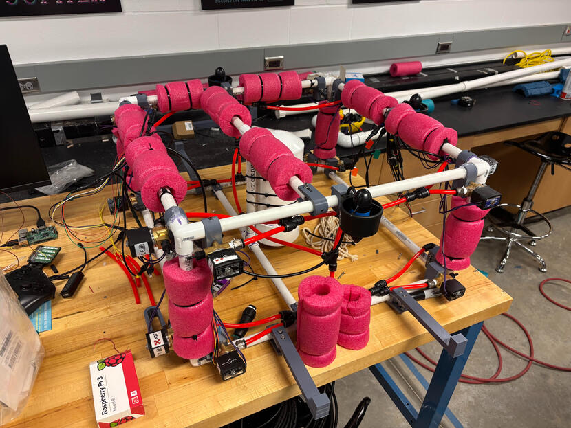
OBJECTIVE: Design and construct a model CubeSat for testing in a neutral buoyancy tank with the goal of undocking, maneuvering to photograph a target, and successfully redocking with the station.
ROLE: Propulsion Systems Lead, Structures and Docking Construction
- Developed and constructed the propulsion system, while leading the physical construction of the spacecraft and docking system.
- Collaborated with subsystem leads to coordinate mechanical interfaces and integrate the various systems into a functional model spacecraft.
KEY CONTRIBUTIONS:
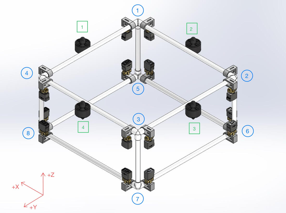
- Developed a hybrid propulsion system consisting of 4 electric motors and 16 solenoid valves to provide thrust and attitude control within the neutral buoyancy environment.
- Designed and fabricated custom mounts to integrate propulsion hardware and other subsystem components within the limited volume of the CubeSat.
- Constructed the model spacecraft, integrating structural components, propulsion hardware, and subsystem equipment.
- Constructed the docking station base required for the model space craft to return.
ENGINEERING CHALLENGES:
- Selecting a propulsion architecture capable of providing the required thrust, maneuverability, and controllability while operating within the constraints of a neutral buoyancy environment.
- Integrating a large number of propulsion components and supporting hardware into the limited spacecraft volume.
- Developing and constructing a docking system that could reliably interface with the spacecraft while allowing the vehicle to maneuver freely in the neutral buoyancy environment.
- Adapting the system design when propulsion hardware did not perform as expected within the project timeline.
APPROACH:
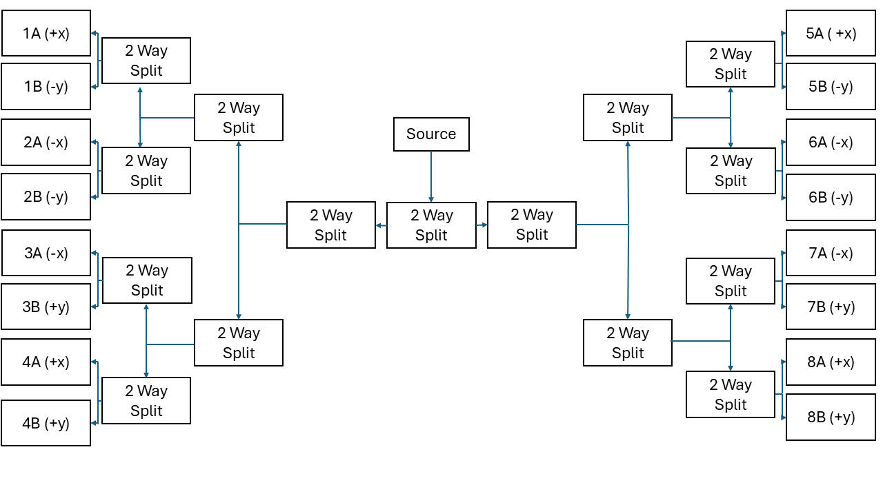
I began by researching and evaluating propulsion concepts based on the mission's requirements for thrust, maneuverability, controllability, and compatibility with the neutral buoyancy environment. After discussing the available approaches with the other subsystem leads, I selected a hybrid propulsion architecture combining electric motors with solenoid-controlled air propulsion. The following diagram details the air flow in the solenoid propulsion system.

Airflow Diagram
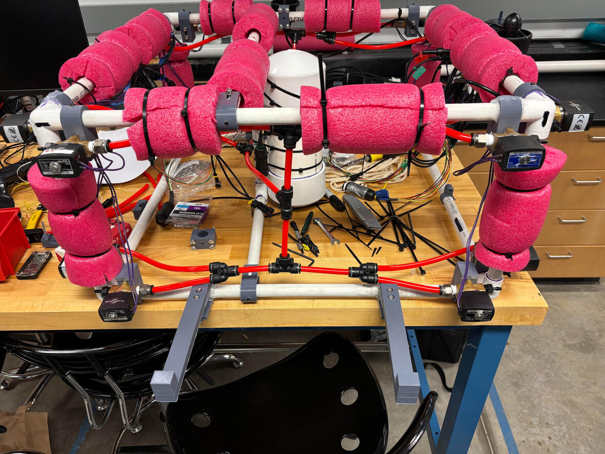
I then assisted in designing and fabricating custom mounts to integrate the propulsion system and other hardware into the spacecraft frame. Component placement was coordinated with the other subsystem leads to ensure adequate space, accessibility, and compatibility between systems. The following picture shows various 3D printed components, including solenoid mounts, camera mounts, adjustable pipe connectors, and docking hardware.

CubeSat CAD Model

3D Printed Hardware
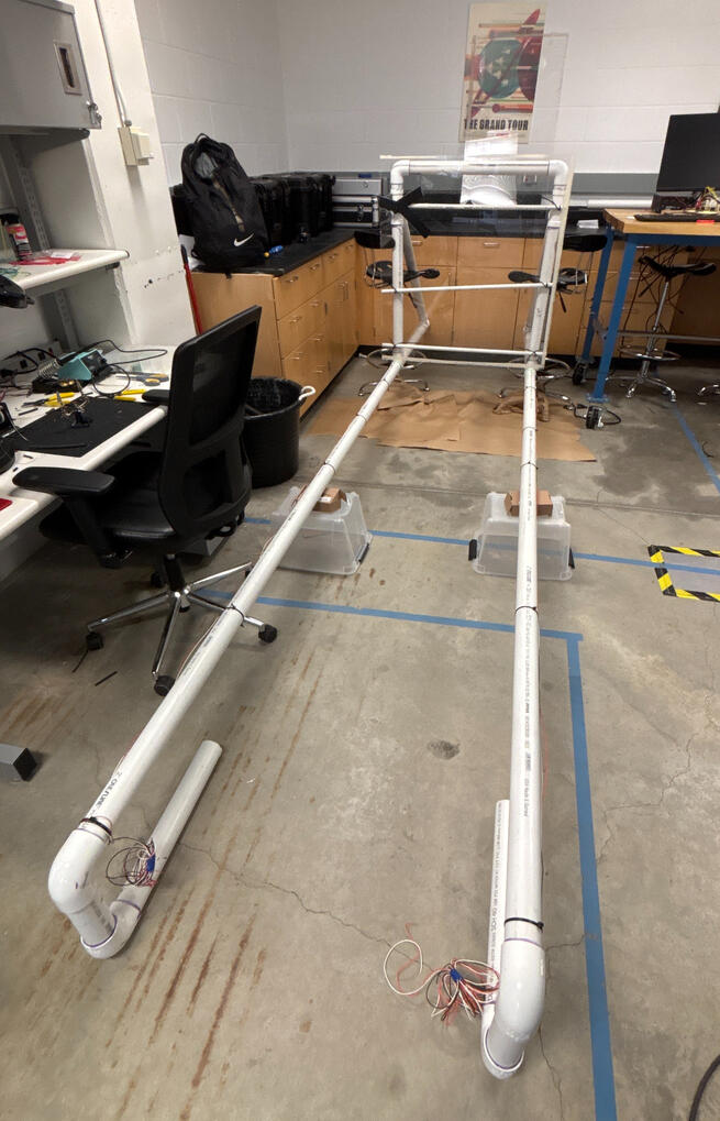
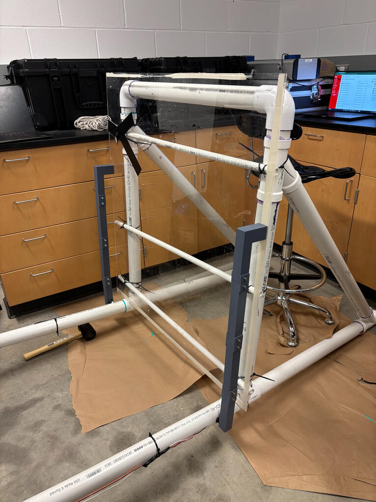
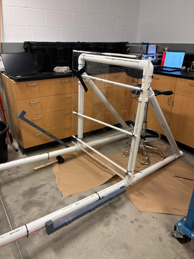
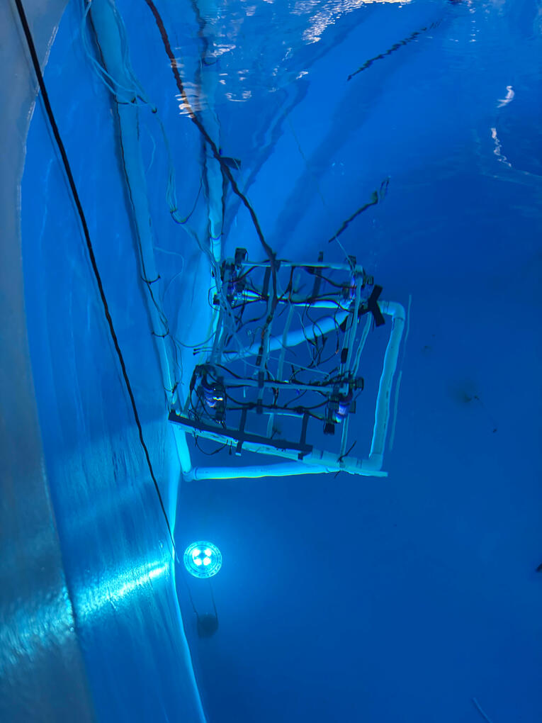
The propulsion, structural, and docking systems were tested throughout the construction process. Testing was performed incrementally to identify fit, integration, and functional issues early, allowing the design to be modified as necessary. The docking mechanism is shown below.

Full View of Docking Station

Docking Arms Down

Docking Arms Up

Docking Station in the Tank
RESULTS:
The completed spacecraft successfully demonstrated the mission sequence of undocking, maneuvering to the target, capturing a photograph, and returning to the docking station, although the final propulsion configuration differed from the original design.During testing, the purchased electric propulsion motors were found to provide insufficient performance and were ultimately determined to be ineffective for the intended application. With the project timeline preventing replacement hardware from being procured and tested, the team adapted the system rather than abandoning the original mission objective.

The Adapted System
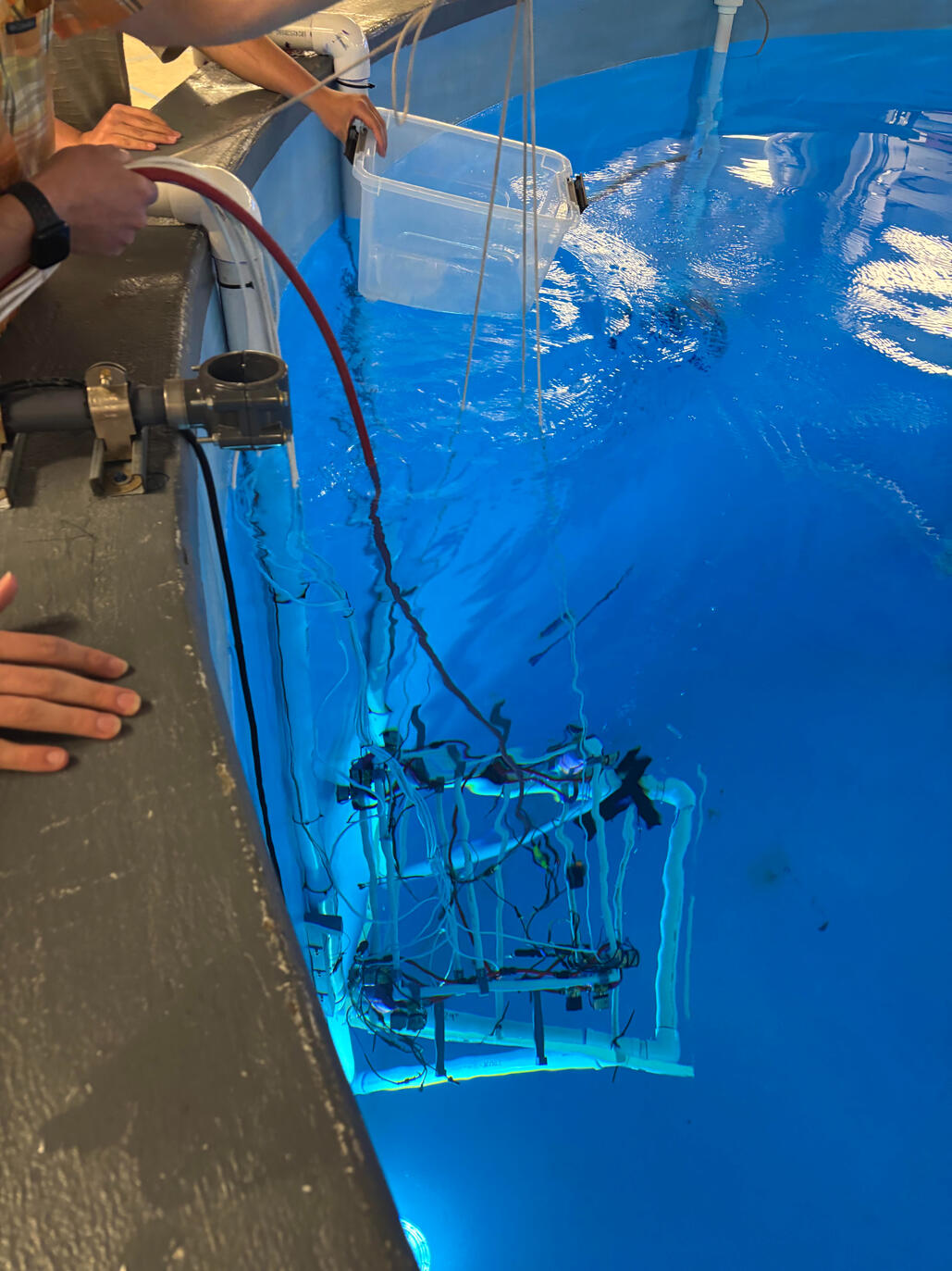
The final configuration used a simplified mechanical method to constrain spacecraft elevation while retaining solenoid-based propulsion for maneuvering. This allowed the team to continue testing the spacecraft's horizontal maneuvering and docking capabilities despite the loss of the primary electric propulsion system.

The Team
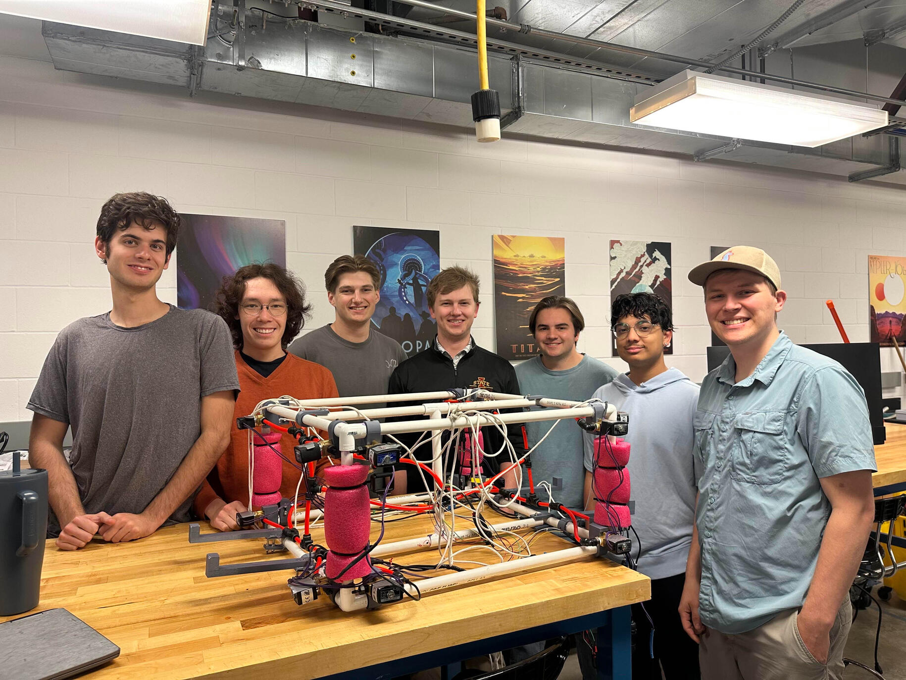
The experience reinforced the importance of hardware validation, contingency planning, and adapting engineering solutions to real-world constraints. The project provided hands-on experience taking a system from concept through fabrication, integration, testing, and design iteration.
TECHNOLOGIES & SKILLS:
- SolidWorks
- Mechanical Design
- Small-Scale Structural Construction
- Propulsion Systems & Systems Integration
- Prototyping & Testing
FLIGHT TRACKER - PERSONAL PROJECT
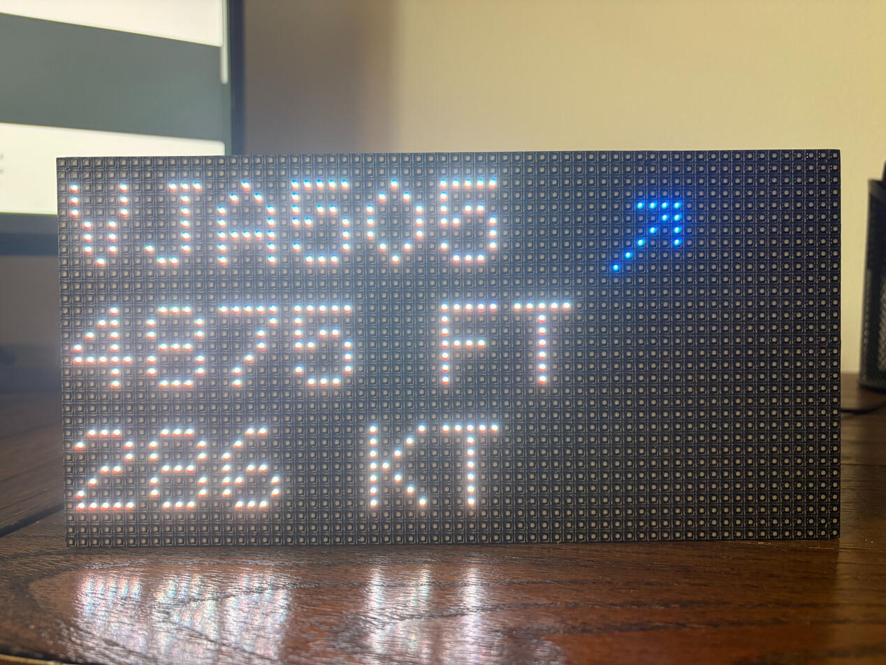
OBJECTIVE: Display commercial aircraft data regarding arrivals and departures in proximity on a LED matrix board.
ENGINEERING CHALLENGES:
- Obtain accurate and up-to-date flight data and information
- Display flight data in an informative, efficient, and continuously updating manner
APPROACH:
I began by researching the hardware and software requirements for a standalone flight-tracking display, including the Raspberry Pi, RGB LED matrix, interface hardware, power requirements, and available flight-data APIs. After selecting the components, I assembled the system and configured the Raspberry Pi for development.

Hardware Configuration
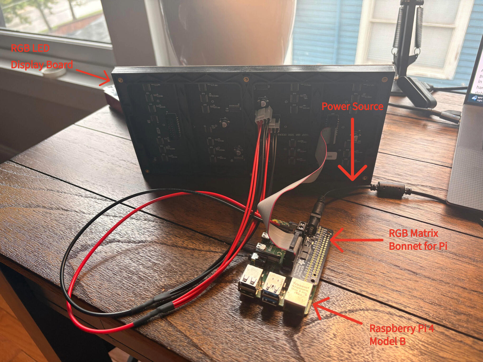
Development was performed in two distinct stages, allowing for testing of each major component independently before integrating to complete the system. I first developed the flight data application to connect to the OpenSky Network API, retrieve incoming and outgoing aircraft data, and parse the relevant information. Seen below is the output of a test ran to pull flights and display them.

Software Testing
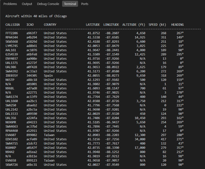
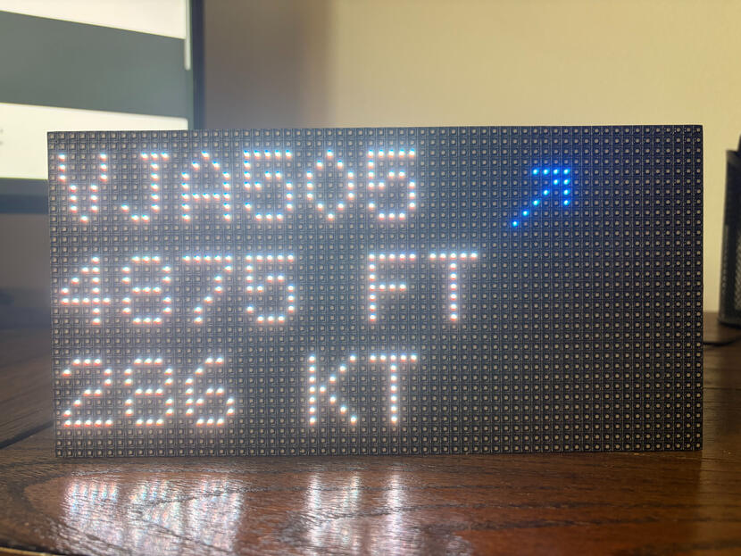
Separately, I developed test code for the RGB LED matrix to verify communication with the display and establish the formatting and scrolling behavior for flight information. I ran a test with static text to ensure the display board was interacting correctly with the Pi, as well as to adjust small details, such as text size, color, and spacing. The following video shows the display board during a successful test.
After successfully verifying that each stage was working, I combined them into a standalone flight-tracking display. The final product continuously retrieved aircraft information from OpenSky and displayed incoming and outgoing flights on the LED matrix in a readable, continuously updating format. The project provided hands-on experience with embedded systems, hardware/software integration, API integration, real-time data processing, Linux-based development, and iterative testing and debugging.
TECHNOLOGIES & SKILLS:
- Python
- C/C++
- Git
- 3D Printing
- Hardware/software integration
SCOOP HOLDER
OBJECTIVE: Design and manufacture a mounting and organizing system for ice cream scoops used in the Iowa State University Creamery retail store. Improve the organization and usability of the scoop holder system while addressing food safety, durability, cleaning, and manufacturing requirements.
ROLE: Designer & Manufacturer, ISU Creamery Associate
- Combined firsthand experience working in the Creamery with mechanical design and modeling skills to develop a custom scoop storage system.
- Worked directly with Creamery employees to identify requirements and translate operational needs into a practical, manufacturable design.
KEY CONTRIBUTIONS:
- Gathered requirements directly from Creamery employees, identifying operational, food safety, cleaning, durability, and space constraints.
- Designed the system in SolidWorks, iterating component geometry and interfaces to accommodate the existing freezer and metal storage components.
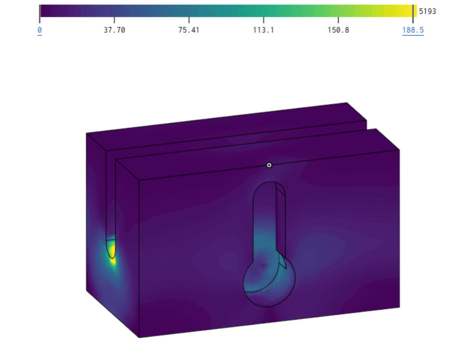
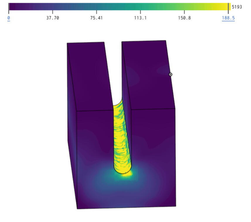
- Performed FEA to evaluate structural loading and impact conditions, using the results to refine the design.
- Manufactured the components using 3D printing and iterated the design based on prototype testing and real-world use.
- Installed and implemented the completed system in the Creamery retail environment.
ENGINEERING CHALLENGES:
- Meeting food safety and allergen-control requirements while allowing multiple scoops to be stored without contacting one another.
- Designing a system that could withstand the repeated impacts and loading associated with scoops being rapidly placed and removed during peak business hours.
- Developing components that could be easily disassembled and cleaned on a regular basis.
- Designing components around the 180 × 180 × 180 mm build volume of the available Bambu Lab A1 Mini 3D printer.
APPROACH:
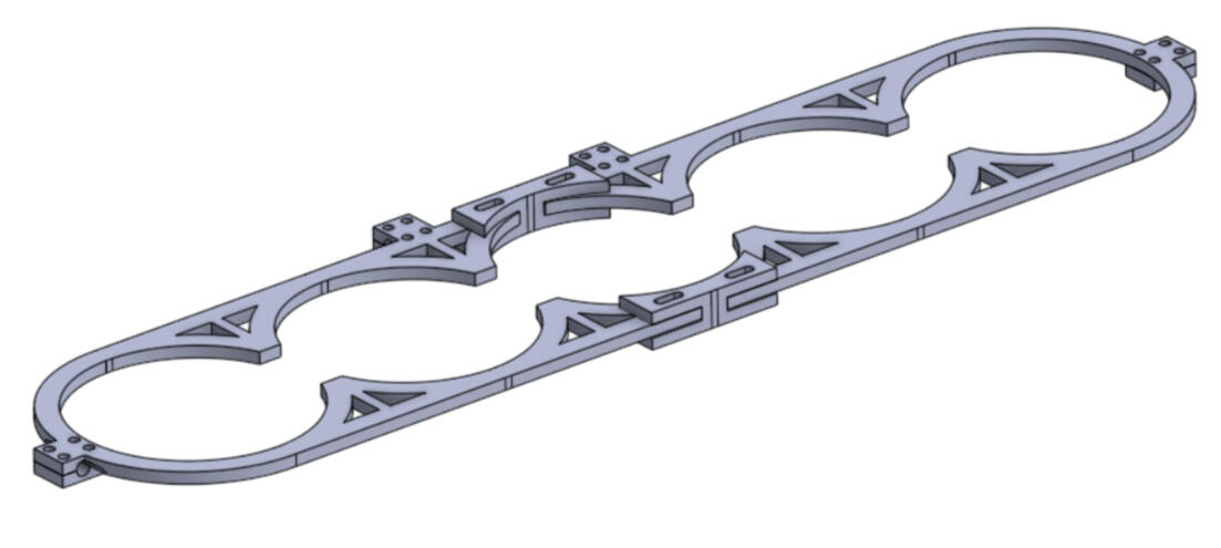
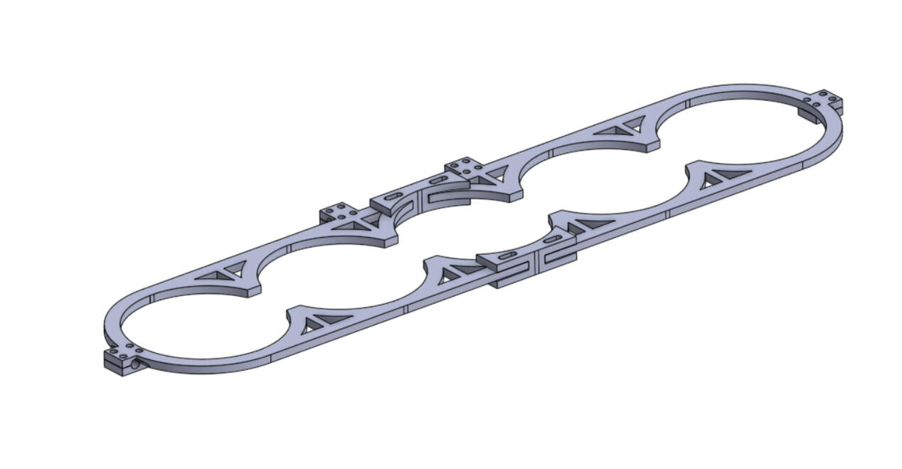
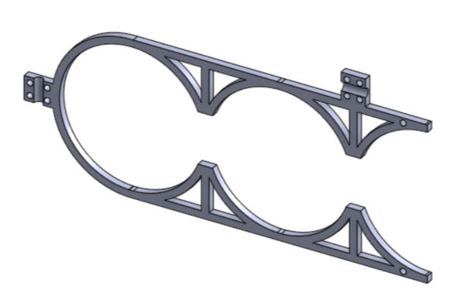
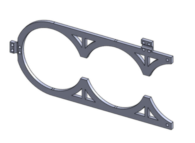
Requirements → Concepts → CAD → FEA → Prototype → ImplementationRequirements were established through employee input and observation of the existing workflow. Key considerations included scoop separation, cleaning, durability, accessibility, manufacturability, and printer limitations. The following pictures show early concepts of the main apparatus.

Initial Concept
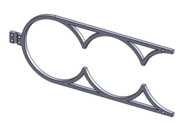
2nd Iteration
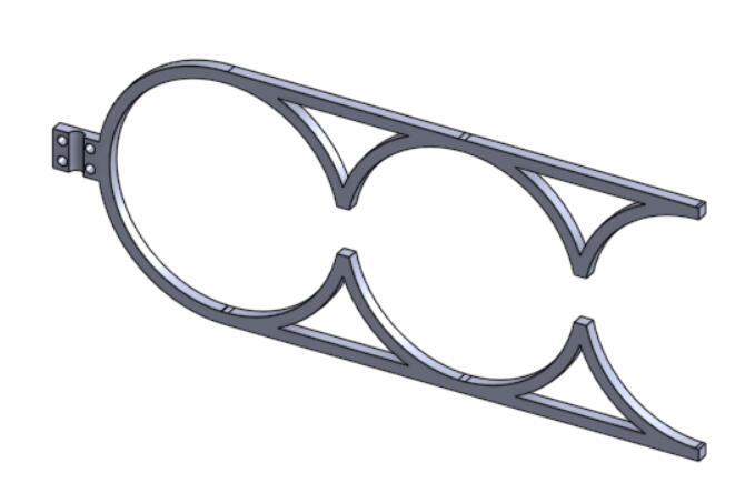
3rd Iteration
4th Iteration
Final Iteration
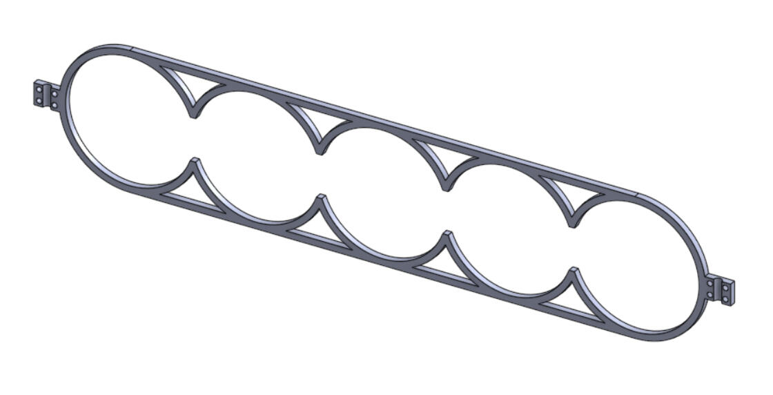
Multiple concepts were compared based on functionality, manufacturability, cleaning, durability, and installation. A modular design was selected to simplify manufacturing, assembly, and maintenance. Components were designed in SolidWorks to interface with the existing freezer and metal basket.
FEA was used to simulate loading and identify areas of potential concern. Components were then 3D printed and tested for fit, accessibility, assembly, and structural performance. The following pictures show FEA simulations for the mounting block.

Iso View of Key Slot

Custom Iso View
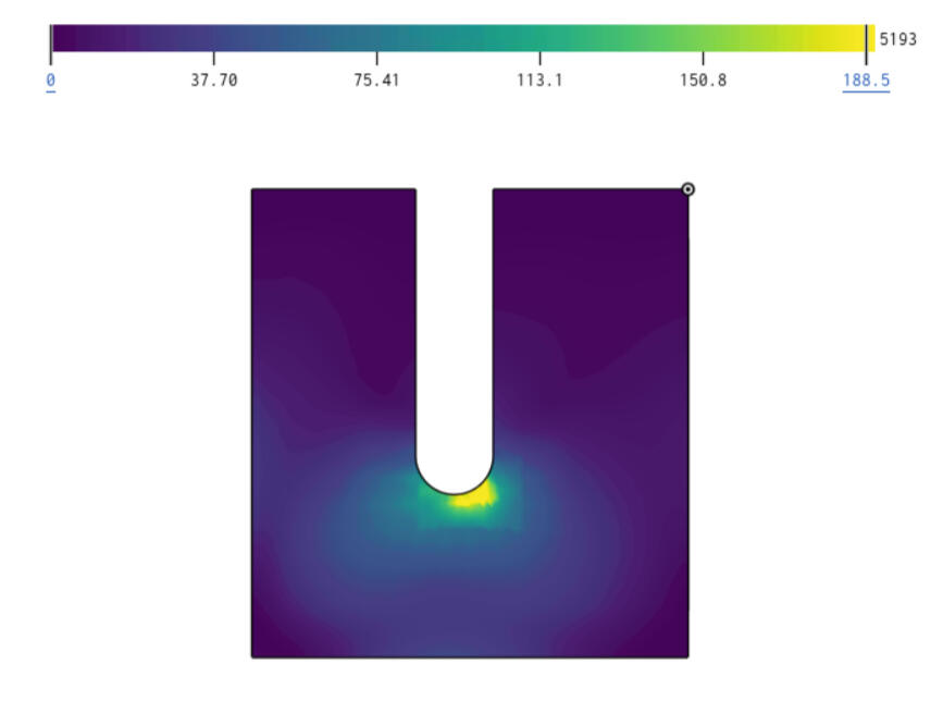
Right Side View
The final components were assembled with hardware and installed in the Creamery retail store for regular use.

Final Assembly
RESULTS:
The project resulted in a functional, custom-designed scoop storage system that was manufactured, installed, and used in the Creamery retail environment.- Separated individual scoops to reduce cross-contact concerns.
- Allowing components to be easily removed for cleaning.
- Utilized existing metal hardware to simplify installation.
- Withstood repeated loading during normal operation.
- Fit all printed components within the available printer volumeThe project demonstrated the complete engineering process from gathering requirements to design, analysis, prototyping, manufacturing, and implementation.
TECHNOLOGIES & SKILLS:
- SolidWorks
- FEA
MARVEL - MARTIAN ASSESSMENT OF RADIATION VARIABILITY AND ENERGY LEVELS
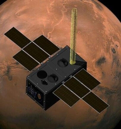
OBJECTIVE: Design a small-satellite mission to assess variations in solar radiation and energy levels around the Martian surface and investigate their potential effects on human health and electronic systems. Develop a preliminary mission architecture addressing all necessary parameters.
ROLE: Propulsion System Lead & Structures System Lead
- Developed and evaluated propulsion concepts to meet orbital and mission-duration requirements.
- Designed the spacecraft structural architecture around mass, launch constraints, subsystem integration, and the Martian environment.
- Performed system-level trade studies and analyses to balance propulsion requirements, structural mass, and scientific payload needs while coordinating interfaces with other subsystem leads.
KEY CONTRIBUTIONS:
- Developed a MATLAB orbital-decay analysis script to quantify expected altitude loss and determine whether an active propulsion system was necessary for mission success.
- Evaluated multiple propulsion options, including cold-gas thrusters, electric propulsion, and a no-propulsion configuration, ultimately eliminating propulsion based on mission requirements and calculated orbital decay.
- Evaluated 6061-T6 aluminum and composite materials through a structural trade study considering strength-to-weight ratio, radiation shielding, manufacturability, accessibility, and combability with thermal requirements.
- Contributed to the selection of mission orbit parameters, using STK to simulate orbital coverage and confirm suitability for the scientific mission.
ENGINEERING CHALLENGES:
- Determining whether the mission required an active propulsion system to maintain an acceptable altitude over its operational lifetime.
- Selecting a structural material capable of satisfying strength, mass, environmental, thermal, and radiation requirements.
- Selecting an orbital configuration that provided sufficient surface coverage while maintaining suitable operating conditions for the scientific instruments.
- Balancing competing subsystem requirements within a preliminary spacecraft architecture.
ENGINEERING ANALYSIS & DESIGN:
Because MARVEL was a hypothetical mission, the design process focused on establishing requirements, developing concepts, performing trade studies, and using analysis to justify major design decisions.
The primary propulsion requirement was to maintain the spacecraft at an acceptable orbital altitude throughout the mission's yearlong operational period. I evaluated three approaches: cold-gas propulsion, electric propulsion, and eliminating propulsion entirely. Orbital decay was identified as the primary factor in determining whether propulsion was necessary. I developed a MATLAB script to estimate the expected orbital decay and calculated an altitude loss of approximately 1.8 km/year under the assumed mission conditions.

Orbital Decay Vs. Time

Required Thrust Vs. Time
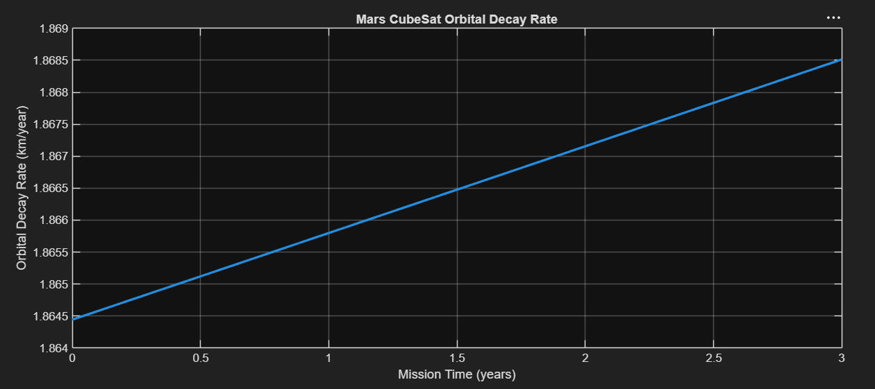
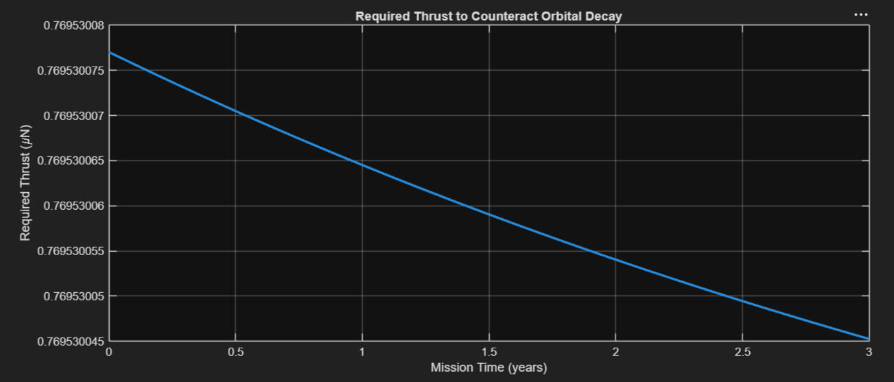
Given the calculated decay rate and the scientific payload's tolerance to small changes in altitude, the expected loss was determined to have a negligible effect on the mission. The team therefore eliminated the propulsion system, reducing spacecraft mass, complexity, and potential failure points.
| Concept | Advantages | Disadvantages | Decision |
|---|---|---|---|
| Cold Gas | Simple, high thrust | Added mass/complexity | Rejected |
| Electric | High efficiency | Low thrust | Rejected |
| No Propulsion | Lowest mass/complexity | Orbital Decay | Selected |
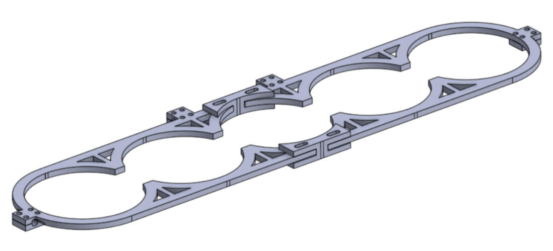
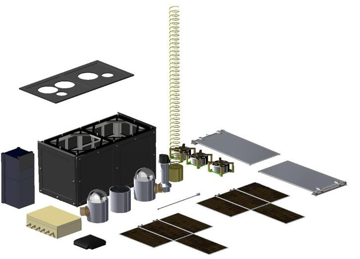
The structural system was designed to provide adequate durability and subsystem support while satisfying the mission's dimensional, mass, launch, and environmental requirements. Key constraints included a maximum stowed envelope of 226.3 × 226.3 × 454 mm, a maximum launch mass of 30 kg, and compatibility with the selected deployment system. I evaluated composite materials and high-strength aluminum alloys as potential structural materials. The final design utilized 6061-T6 aluminum, selected for its favorable strength-to-weight ratio, established aerospace applications, manufacturability, accessibility, and compatibility with the spacecraft's thermal and environmental requirements.

Exploded View
In addition to my primary propulsion and structures responsibilities, I contributed to selecting the mission's orbital parameters. Based on the operating requirements of the scientific instruments, the team selected a 450 km polar orbit around Mars. STK was used to simulate the proposed orbit and evaluate surface coverage. The analysis indicated that the selected polar orbit could provide near-complete coverage of the Martian surface over the mission period, supporting the scientific objectives of the mission.
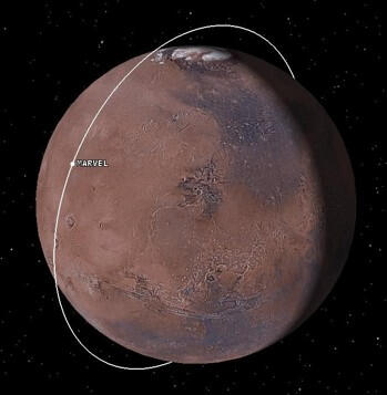
Isometric View of Orbit
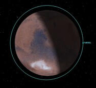
Straight View of Orbit
TECHNOLOGIES & SKILLS:
- MATLAB
- Systems Tool Kit (STK)
- SolidWorks
- Orbital Mechanics